Description
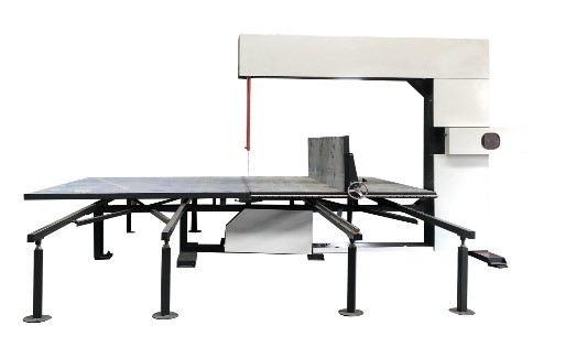
The vertical foam cutting machine consists of the following parts:
This machine consists of main components such as the frame, base, working table guide mechanism, mobile positioning plate, motor drive mechanism, blade tension adjustment mechanism, blade wheel mechanism, blade sharpening grinding wheel mechanism, and blade wheel safety cover.
The frame and base are constructed from welded steel sections, and the blade wheel mechanism is installed on the same plane as these components. To ensure the stability of the blade wheels, they undergo static balance tests before being fixed to this part, and they should not be repositioned once installed and calibrated.
The working table is composed of a square frame and aluminum composite panels, with a mobile positioning plate on top. It moves along the longitudinal guide rails, enabling the cutting motion to advance and retreat. The mobile positioning plate is responsible for controlling the cutting thickness.
The blade tension adjustment mechanism is used to adjust the tension of the blade and to facilitate the installation and removal of the blade. When in use, it is used in conjunction with the spring-tightening nut in this component, which allows for adjusting the tension of the spring.
The blade sharpening grinding wheel consists of two opposing bowl-shaped grinding wheels driven by an electric motor. They gently touch the blade edge and are fixed after a certain angle offset, which can be selected by the operator, typically ranging from 15° to 30°.
Regarding the installation and removal of the blade, there are chain-link mechanisms located on the front and rear sides of the working table. These mechanisms serve both as a connection between the left and right platforms and as a means for disassembling and assembling the blade when a new one needs to be replaced. To change the blade, one must first detach these chain-link mechanisms before removing the blade.
To ensure proper blade positioning, the blade wheels are installed on the same plane during the installation to prevent the blade from slipping or deviating during operation. To prevent radial blade movement, a set of bearings is installed under the top beam to support the blade wheel shaft, and an identical set of bearings is installed in the base (under the working table) to assist in blade positioning.
| Model | SABVC-1320 | SABVC-1720 |
|---|---|---|
| Inside worktable size | W1200mm*L2290mm | W1720mm*L2290mm |
| Cutting thickness | 3~mm | 3~mm |
| Cutting height | H800/1200mm | H800/1200mm |
| Blade length | L7320mm/L8100mm | L8100mm/L8900mm |
| Total power | 1.74kw | 1.74kw |
| Machine weight | 1300kg | 1500kg |
| Machine external size | L4500×W4000×H2550mm | L4500×W4800×H2550mm |

